I2C Connection Working!
Been a while since the last post! Here it goes!
We currently have three students working on the project. We had a fourth last spring, but she has since graduated. For the rest of us left, we now have specialized tasks to help move the project forward on all sides. Here the specialized tasks:
- Courtney Allen (HCI) works on the physical components of the circuit.
- Noah Sutter (CS) works on the programming for the buttons and LEDs.
- Sarah Schoemann (DM) works on the physical fabrication of the quilt.
When we last left the project, the LEDs were failing to stay on and communicate with the master microcontroller. After some diligent testing to make sure the LED strips weren’t blown, we discovered that the LEDs were actually not receiving enough power. It was at this stage when the specialized tasks came into play. Courtney investigated similarly large-scaled LED projects to discover that not only was there not enough power but the wires being used weren’t capable of the traversing power needed AKA we were on track to start something on fire. Since the discovery, the team has reached out to another group working successfully on a large-scale LED project on campus. With the other group, our main contact is with Noah P. (a different Noah than the one on the team) and he helped set up our next steps, which included scaling down our project.
That’s where the project finished off in the fall. Courtney converted the large 30×30 grid of LEDs into a 5×5 grid of LEDs; Noah adjusted the code to fit the new layout while keeping the code scalable for the next steps. After some testing and checking of the wired connections and the direct, now appropriately amped power supply, the interaction was functional for the first time since a year and a half ago and the very first time for the current group of students on the project! Getting ambitious, Noah extended the code to create a 5×30 grid, where 30 pixels on each of the 5 strands were connected and correctly responding to the button presses. The code will be broken down further in another post.
Here’s the project working on the 5×30 grid:
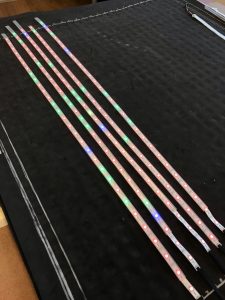
The LED strips turned on by way of pressing the capacitive “quilt” underneath (the dark piece underneath the strips).
It’s working!
Link to video of 5×30 Grid Working!
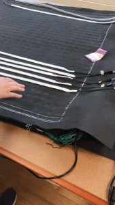
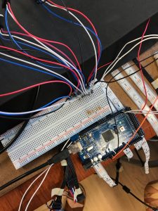
So, the next steps are to create a modular layout of the Neopixel strips. We have 30 total to power, but our power source can only power 5 strips at a time. As such, we are dividing up the 30 strips into 6 sections. One tricky part of creating a modular setup is to make sure all of the data pins from the Neopixels have a resistor and have long enough (but not too long) wire to connect; if the wire is too long, the resistant from the length will cause communication issues and then the strips won’t light up correctly. Another tricky part of the aimed modular setup requires the system to be easily dismantled and easily reassembled, which directly affects the connections and types of wires being used within the system. Currently, the wires work for the set of 5 strips, however the system is not stable and does not hold very well to movement.
Here’s how the testing setup is laid out:
The temporary scaled-down setup for 5 strips of LEDs.
As you can see, the ground is also connected to the Arduino, though the strips and the microcontrollers each have individual power sources. In order to complete the circuit, all grounds have to be connected to each part of the system, adding another layer of complexity to the modularity goal.
Luckily, nothing should explode, and coming soon, a post will be about testing a more modular setup for the LEDs with the entire system, as well as the break down of the code being used.