LED Wiring
The LED strip has three inputs: +5V, Gnd, and data input. The data input has to come from one end of the strip, indicated by the arrows.
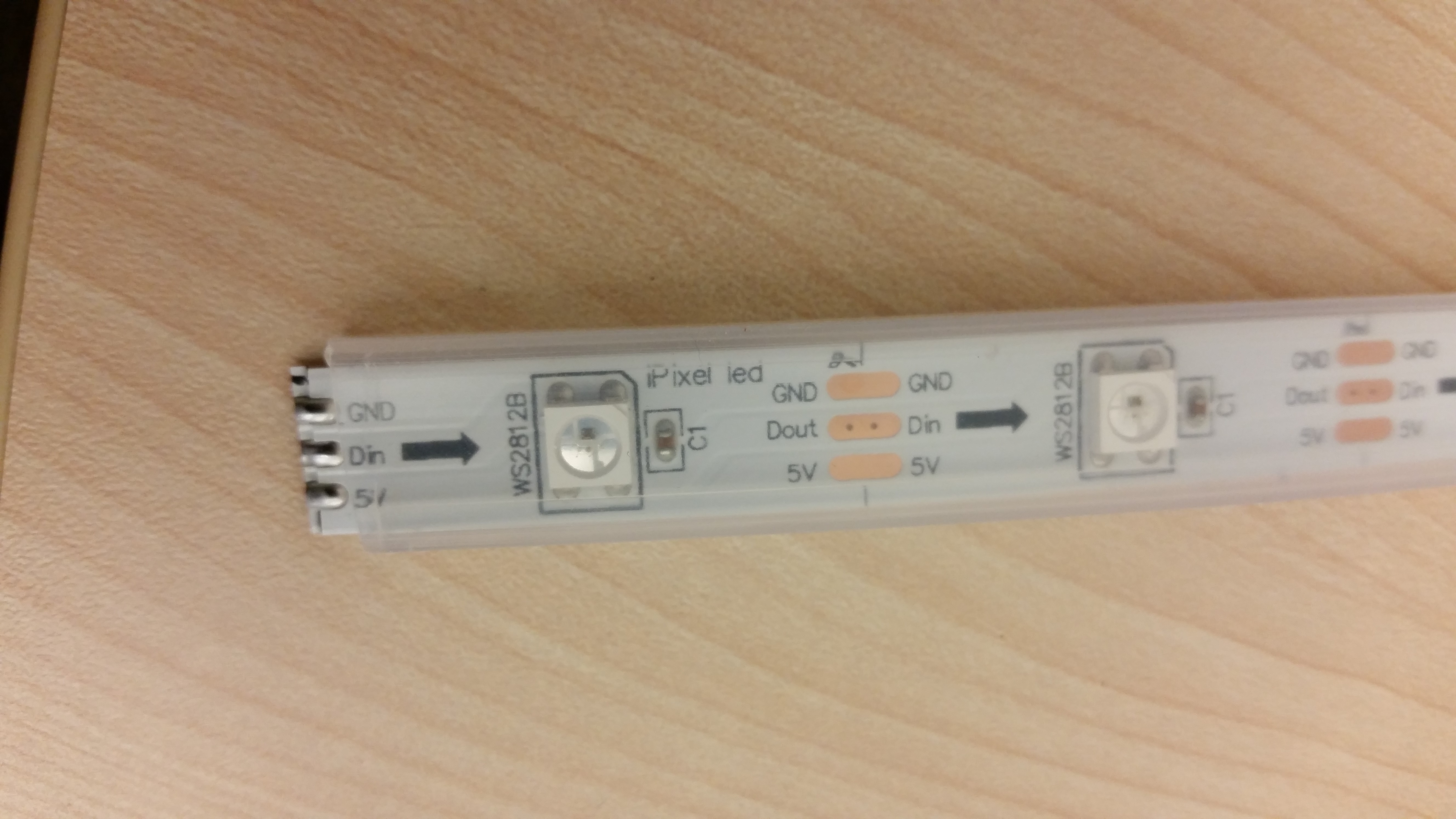
The power for the strip can come from any end. The +5V needs to be connected to 5 volts power supply. The Ground needs to be connected to both, the ground from the power supply and to the ground pin in the Arduino mega. The data input needs to be connected to Arduino mega through 470 Ohms resistor.
Also the neopixel guide suggests to put 1000 microfarad capacitor in parallel with power. In this case two 4700 microfarads are being used for 10 led strips.
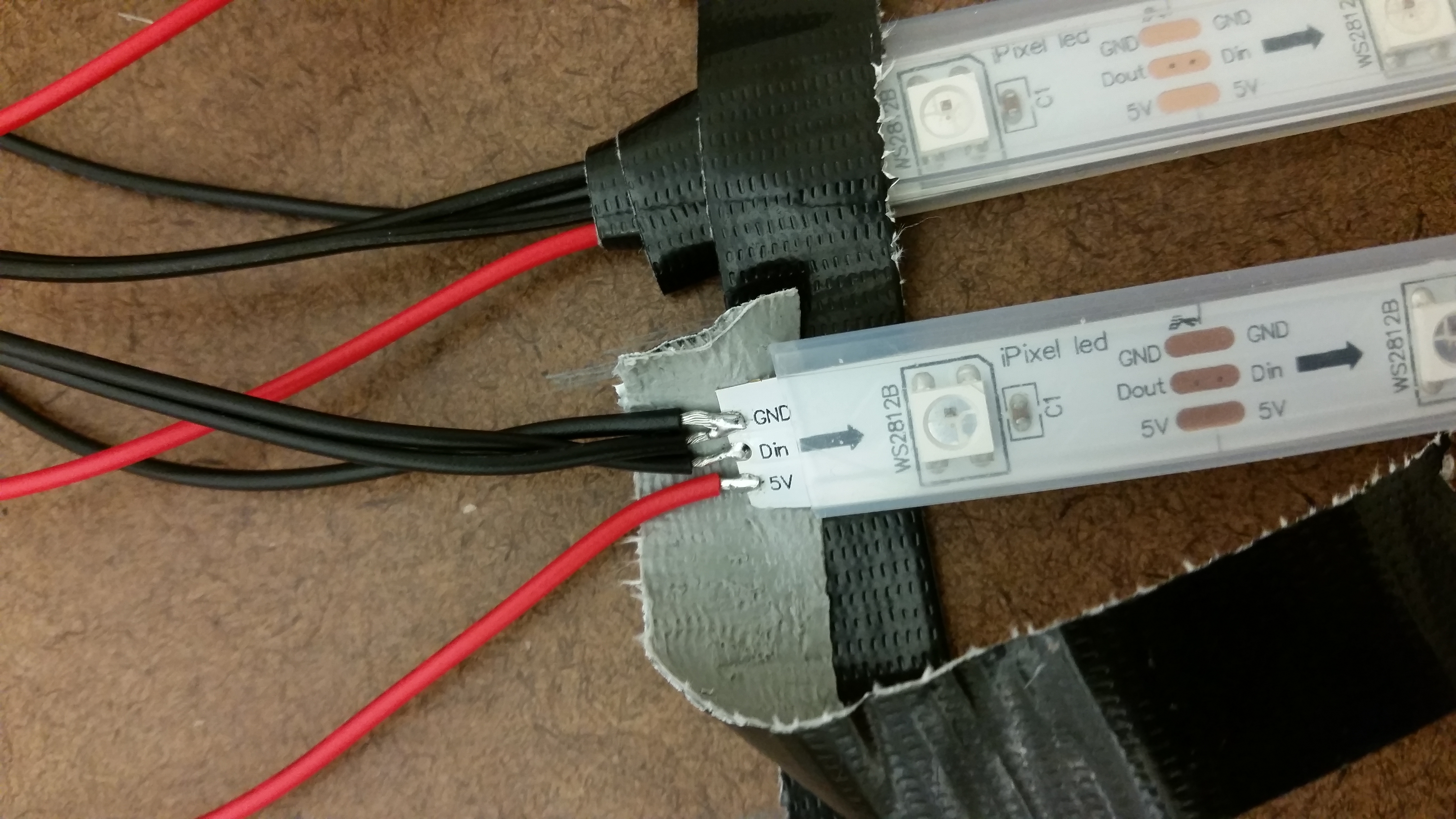
The resistor has been soldered to the wire and is covered by shrink tubing.
In order to power all 30 strips, terminal strips are used to distribute the power. The first terminal strip is connected to the power supply and is used to split the power to another three terminal strips.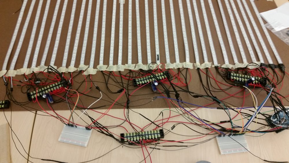
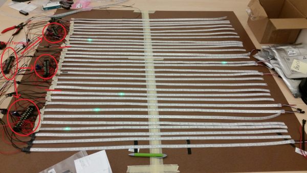
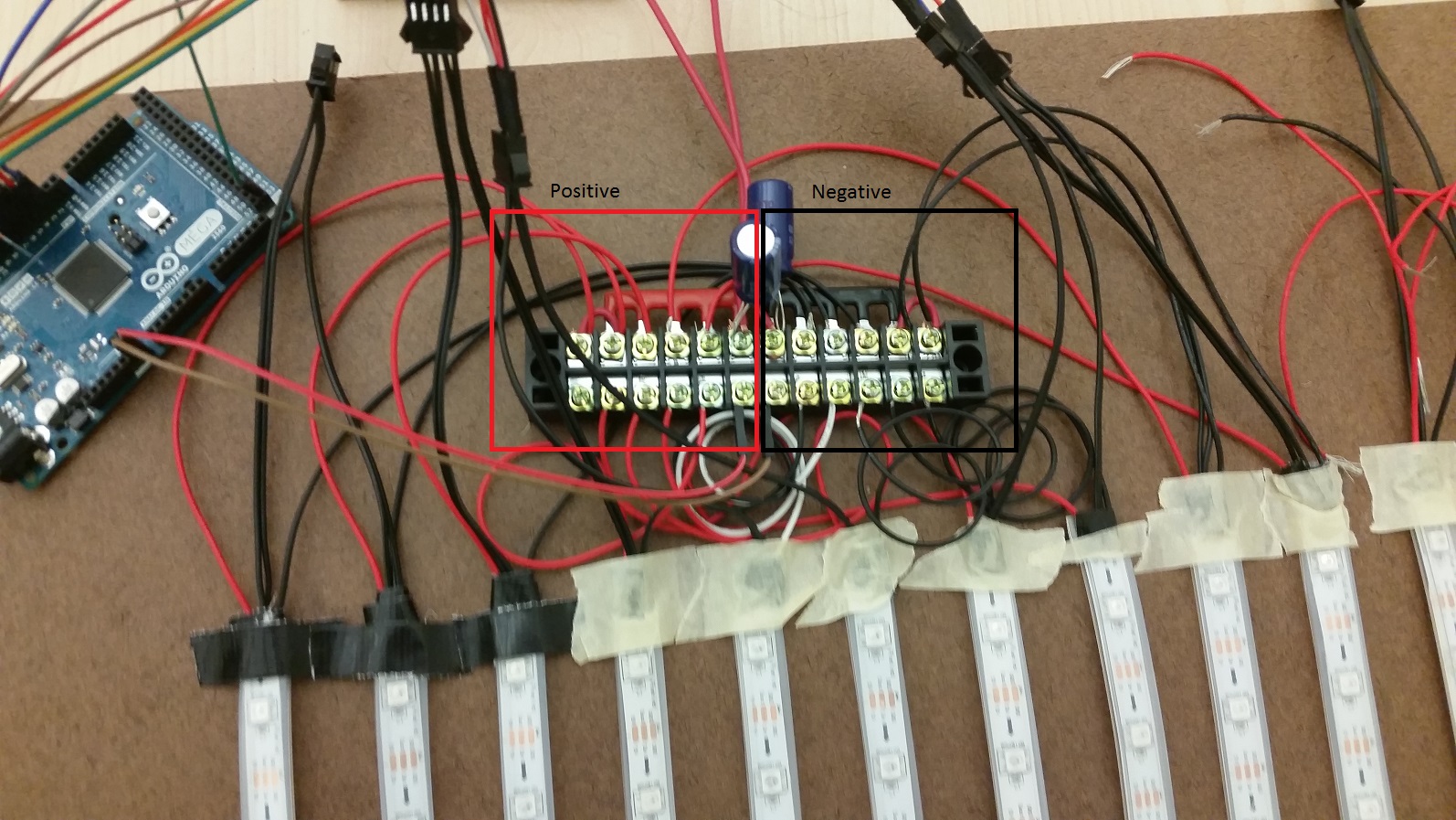
Each of the second terminal strips can host 11 connections. 10 are used by the LED strips and then the extra one can be used to power Arduino mega. On the terminals where the power is connected to the strip, two 4700 microfarad capacitors are placed.
The strip itself is separated into positive and negative parts.
The neopixel guide recommends to use 20 – 60 mAmps per pixel. Since there are 900 pixels the total current should be 18 – 54 Amps. But I found that using one 10 Amps power supply is more than sufficient to power all the pixels at about 1/3 brightness. But incase that is not enough a second power supply can be connected to the main terminal strip.