The code that runs behind FloorChart
Floor Chart Code
The Floor Chart is a 30×30 grid of buttons and matching 30×30 grid of LEDs. Each button is underneath an LED. The floor chart code can be thought of at a high level as taking input from the buttons and translating those into color changes in the LEDs. The ultimate goal is that clicking a particular button results in the cycling through a set of colors for the corresponding LED.
The 30×30 grid of buttons is made of 30 vertical strips overlaid on 30 horizontal strips. When pressing a particular place on the grid, one vertical strip and one horizontal strip will connect completing a circuit. This connection can be read as inputs to the digital pins on the arduino. Furthermore, the leds can be controlled through digital pins on the arduino turning them on and off and changing the colors. Each arduino has about 50 of these digital pins. Because of this limited number of digital pins, it would not be possible to hook up all 60 metal strips and the 30 LED strips. For this reason the 60 metal strips are broken up in half. So one arduino reads the input from 30 horizontal strips and 15 vertical strips, this means one arduino can read 450 of the 900 total buttons. So there are two arduinos reading in inputs from buttons.
Once these two arduinos get the button input, they need a way to relay that information to the corresponding LEDs. The way they do this is by sending that information to a third arduino that then relays that information to the LED on one of the 30 LED strips that matches up with the button that was pressed.
The Details
The code to do what was described above is broken down into three parts. The code that controls changing the color of the LEDs (the Master code), the code responsible for reading button presses in two separate arduinos (Minion code), and the code that supports reading button presses by reading changes in the current of the strips.
master.ino
The Master code is run on the arduino that changes the color of the LEDs. The Master code is called Master because it is responsible for all communication between arduinos as well as changing the color of appropriate LEDs. In order to change the color of specific LEDs the Master must first get information about button presses. It does so by setting up an I2C connection with the two Minion arduinos (arduinos that read button input) and polling each of the minions at intervals to see if they have received any button input. If the minion has observed any button input it will tell the Master by sending a payload over I2C that contains the address of the Minion, the row and column of the metal strips that changed state as well as the type of state change such as pressed or released (discussed further in Minion section). If there is no button input, the Minion will send an empty payload.
The row and column of the button as well as the information about the type of state change it is experiencing can be used to then update the colors of the LEDs. In order to update these LEDs we must have a way to keep track of the state of every pixel. The state of every LED is stored in an array with a slot for every pixel. Each element of the array is an unsigned integer of 32 bits. The most significant 24 bits of this integer store the time of the last interaction with the LED (this supports long presses and other time sensitive button inputs) while the least significant 8 bits store the state of the pixel.
When receiving a button input the Master will look up the current state of that pixel and take the appropriate action dependent on the current state and the input. For example if the pixel is currently green (ex: state 2) and its button gets pressed, it might be the case that the pixel should change to red (ex: state 3). In that case the Master would look up the state of the pixel which would be 2 and change the pixel to red based on that state and the fact that there was a button press. Once the pixel is changed physically, the state is then updated in the pixel state array.
This process of polling the Minions for button input then updating the state of the LEDs both physically and in their state array is repeated on an interval, in this case every 100ms.
masterTest.ino
This code is used to test that all of the LEDs are connected correctly. This code will light up each of the LEDs one at a time, first red then blue and repeat.
minion1.ino/minion2.ino
As stated above, the Minion code is responsible for reading button changes and sending those changes to the master. Each minion takes on half of the button grid to read for changes. The way the Minion reads information from its digital pins is by creating a Keypad which is a set of code that represents the vertical and horizontal strips of metal that make up the button grid and allows the state of each button to be read and repeatedly requesting to update the state of the Keypad.
When starting, each Minion joins the I2C bus with the master and sets up a function to be called when the Master wants information about the state change of buttons. This function grabs a button change from the Keypad containing the row, column, and type of button change. If there was not button change since the Minion last checked, Keypad will return a button change with all 0s for values. This button change is then packed up into a payload with the address of this Minion (used in the Master to adjust rows and columns depending on which half of the inputs the Minion reads), the row and column of the button change, and the type of button state change (press or release).
The Minion continually requests that the Keypad update the state of the input grid and only stops to send button state changes when requested by the Master.
Keypad.cpp/Keypad.h
Keypad is a data structure that supports the Minions in reading the state of the input grid (buttons). Keypad stores the row and column digital pin assignments as well as the overall size of the grid. Keypad also contains a method getKeys() for the Minions to call that updates the state of each of the buttons.
The way the update method works is that it can be called every 10ms max. If it has been at least 10ms since the last time called, it will scan they grid to check for any vertical strips touching any horizontal strips. This is done by sending a current through each vertical stirp one a time and reading the state of each of the horizontal strips to see if they are connecting with the vertical strip that has current running through it. This way the current state of the grid can be found.
Once the current state of the grid has been updated the code compares the current state to the previous state and if there is any change it adds that change to a buffer. The buffer is used as the Master can request button updates slower than the Minion can read button inputs. It could then be the case that the Minion finds two button changes in the time it takes the Master to request a button change. If there was no buffer the Master would only get one of the button changes. Once the button change is added to the buffer the previous state is set to the current state and the process of updating the state of the buttons can start again.
When the Minion requests a button change event, Keypad simply pops the first one off the buffer it has. This change event is the same one that the Minion then sends to the Master.
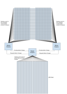
Overall
Overall the Minions keep updating the current state of the grid and find the button changes. The Master then communicates with the Minions to find out the button changes. Once it has a button change the Master then updates the state of the LEDs as appropriate. This process can be seen as drawn below.