Walking Through The Project
We are three new students who joined DILAC lab and are continuing where the project left off from the summer semester. Much of the fall 2017 semester has been a catch up phase to learn about how the project got to its current state and what needs to be done from here. During this process we have spent significant time filling the gaps of knowledge surrounding this project — we will fill you all in too!
Testing the Neopixels
During our learning process, specifically investigating the hardware setup, we briefly turned on the LEDs to see the current conditions they were in. Since some of the wires were no longer connected and seemingly in chaotic order, we merely wanted to see if the LEDs even turned on. Indeed the LEDs turned on but were not lighting how we expected: the colors were random and uneven in intensity. The code suggested they all be uniform at least in light intensity if not also in color. So now we came across an issue of whether or not the LEDs were burnt out from the disconnected wiring, miswiring caused by our investigations, power overload, or just bad LEDs.
To find out the cause, we tested each strip individually, with a different arduino from the project, with RGB color strand test code. Through the testing, only one strip seemed to have discoloration and the cause seemed highly probable that the wiring was weak.
This was great news! Wiring is a simple fix and we had already decided to rewire the hardware setup due to inconsistent coloring choices. We wanted to create a more organized system and by doing so, we can confirm if the one LED strip was discolored due to poor wiring or if it is something else.
During this process of testing we were also able to eliminate a possible cause of a low battery supply/overpowered supply. By using a brand new 9V battery, we compared one strip’s intensity between the two batteries. The wires had to be double checked for connections in the process of changing the batteries out. Once all wires were checked to be in order, the LEDs showed no difference in intensity.
Understanding how the system works
Currently, there are two main components to the project: the membrane touchpad and corresponding LEDs. When someone touches a square on the touchpad, the corresponding LED should come on. Eventually, the system will entail changing the LEDs to specific colors, but we are aiming for “on” and “off” phases first.
How this works:
The Membrane Touchpad
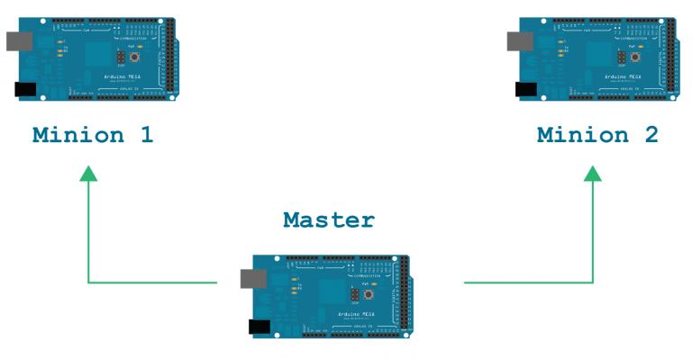
The touchpad consists of one “master” Mega Arduino board linked to two “minion” Mega Arduino boards. The master board is set in the middle with one minion board on either side.
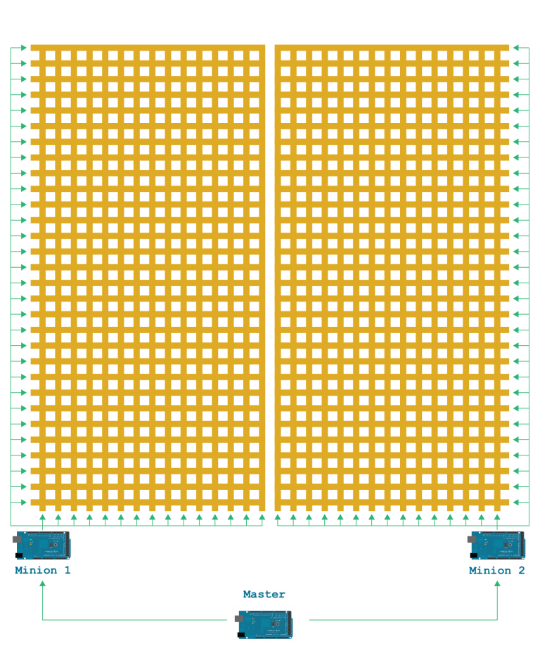
Each minion is connected to 30 rows of copper tape, but only at half-lengths; each minion is also connected to 15 full-length columns of copper tape. Minion 1 is connected to columns 1 thru 15; Minion 2 is connected to columns 16 thru 30. “Buttons” are created by the intersections from the copper tape columns with the rows. Each minion is in charge of detecting 450 “buttons.” The minions then calculate the position of the “button” pressed and send this information to the master. This interaction is generated through the use of the keypad library that is available through open-source.
Issue: The keypad library is not available for such a large scale matrix. Our team will have to modify the original library to create an applicable and successful library for our project.
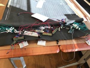
Pictured is a physical picture of the layout of the Master and Minion boards.
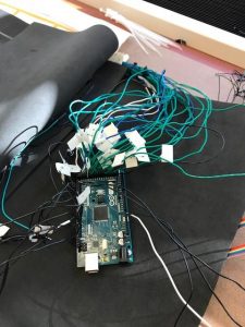
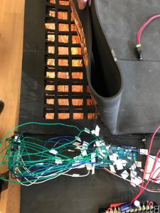
Top: Close up of the copper tape connection to Minion 1. Bottom: Close up of Minion 2.
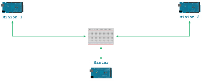
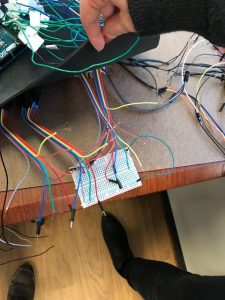
Each minion is connected via I2C bus to the master; the connection is made via pins 20 and 21 on the master: one pin is a data connection and other is clock connection. From our understanding, the I2C bus should prompt an alternating probe between the two minions to the master; the I2C bus is constantly looking for new information while each minion is able to simultaneously report to the master. However, currently the connection is not directly made; the connection is actually made through a breadboard centered in the layout.
Issue: Currently, the I2C bus breadboard setup is not properly connecting both minions simultaneously to the master. As such, the team will have to either solve this issue via software, or develop a new physical setup to properly connect information.
Pictured is the actual connection so far. It is incomplete according to the code.
The LEDs
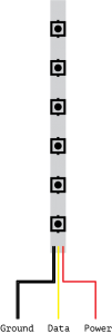
We have 30 strips with 30 LEDs each (900 pixels total). There are four wires attached to each LED strip: (from left to right) two are ground, one is data, and the last is power.
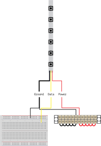
Two ground wires are required in order to ground the LEDs by two methods: through a breadboard as well as through a power block. The data is currently also going through a breadboard in order to be connected to the master board. The power is connected to the same power block as the one ground wire.
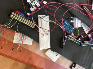
Pictured above is the LED connections to the breadboard. As mentioned already, for each LED, there are two wires going into the breadboard: one ground and one digital.
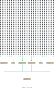
There are two sizes of power blocks, small (holds two strips) and large (holds six strips), and six power blocks total; from left to right the block are large, small, large, large, small, large. These sizes are chosen somewhat arbitrarily, but the blocks better organize the LEDs while keeping the length of wires in mind. We also have one “mother” power block to channel all of the LED’s power blocks to a power source.
Issue: There are currently not enough power blocks to cover all the LEDs. We will need to gain one more power block in order to cover the last LEDs.
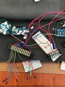
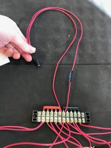
Pictured are the power blocks (Top) and the “mother” power block with its power source connector (Bottom). Currently, the wires connected to the power blocks are all red, which is normally representative of power; but in this case, this is arbitrarily colored and is wiring both power and ground to their respective connections. As an additional note, the capacitors on the power blocks prevent the LEDs from shorting. For now, the amount and strength of the capacitors is a generous guess, but the accurate amount will soon be calculated.
Moving Forward
The team has a few ideas to try out for this semester. We will be trying to match wiring of each power block to individual breadboards and then eventually use permaboard. The permaboard will allow a more permanent system that eventually can become transportable.
Another step towards creating a stable and/or possibly even modifiable system is fixing the the components in place with hot glue or velcro. We can achieve this by laser cutting base pieces to be fastened to the components. In order to better the organization of the system, we will also be breaking up the breadboards, matching the number of the power blocks. As for further developing the LEDs, we need another Mega Arduino or possibly even a Raspberry Pi.
Finally, the team is gaining another member, a computer science major, in order to make progress on the code and connect the LEDs to the entire system!