Why Keyboards Matter
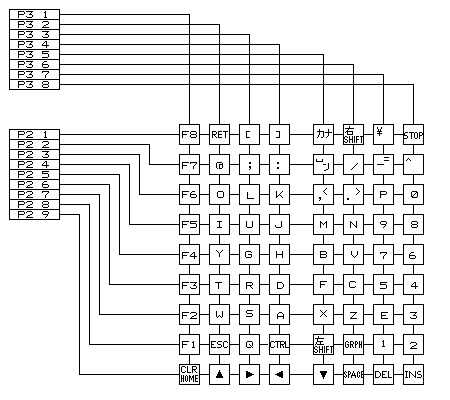
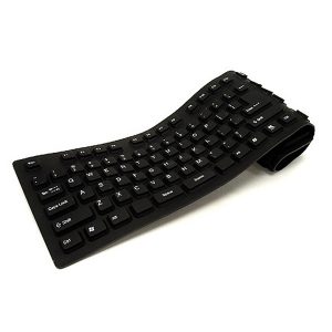
Making a matrix with 9 inputs isn’t all that bad. I wouldn’t mind wiring each one up. But when we get two orders of magnitude bigger to 900, we want something more cleverly constructed, reducing duplicity and manual labor. While Googling one day I looked down to see my hands dancing across hardware with almost 100 inputs and realized: how are keyboards made, and can it help us?
How Keyboards Do It
Luckily, as I suspected, keyboards do not require a unique button at each key. Instead, they use a series of rows and columns that intersect at each key. This handy animation of a circuit diagram explains the structure well:
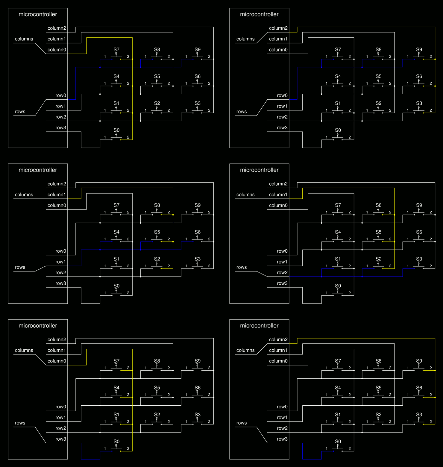
Circuit diagram for microcontroller scanning mechanism on keyboard. Credit Kai Burghardt, WikiMedia Commons
Though simplistic, this schematic more closely resembles a keyboard:
I’m not going to delve into the inner workings of the computer and its keyboard, its hardware interrupts, etc. what is important is that this matrix design, by using intersections, tremendously reduces our hardware requirements.
Looking at the animated diagram, notice the ‘microcontroller’ block – this is exactly what an Arduino is! Let’s say we implemented an Arduino touch pad with this structure, minus ‘S0.’ We would need 3 pins for the columns and 3 pins for the rows, 6 Arduino pins total for 9 unique inputs. Pretty good deal. However, what if we needed 900 unique inputs? Having 30 rows and 30 columns requires 60 pins. This is much better than, say, 1800 – 2700 pins required (without multiplexers) for 900 single buttons.
Possible Implementations
Keyboards are hard (normally). Quilts are soft (normally). We are not trying to fit or not fit into any norms here, but the mechanical keyboards beloved by serious typists: not our target.
On the other hand, flexible membrane keyboards can be useful models.
Our quilt doesn’t need to have flexibility akin to yoga mats (or instructors), but studying the membrane switches in these keyboards can inspire a quilt-appropriate control schema.
Membrane Switches
I’ve always been a fan of How It’s Made. I watch it for fun when it comes on the Science Channel. Of course, after learning about keyboard membrane controllers, I turned to see if my perennial source of manufacturing enlightenment has covered their creation. And of course, it has.
Chronicled below is the making of a control board for an oven from ‘How It’s Made: Membrane Switches.’ You are probably using membrane switches on your oven or washing machine at home right now. However, the oven control board and membrane keyboard’s internal components are very similar – the membrane keyboard simply has dome switches in addition to the membrane to provide gratifying & necessary tactile feedback.
Below, we see that silver conductive ink is screen printed onto plastic membranes.
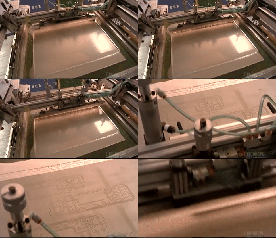
Screen printing silver conductive ink. Credit: How It’s Made
Here, we can view conductive traces up close.
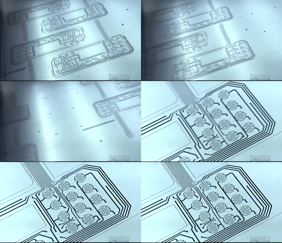
Conductive traces on membrane, detail. Credit: How It’s Made
Lastly, we see an adhesive separator applied to the circuit.
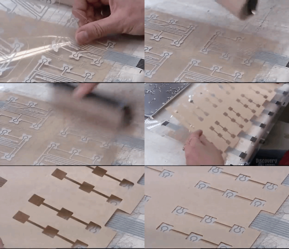
Applying adhesive separator. Credit: How It’s Made
Why is this applied? This can be explained with yet another helpful diagram. The separator can be thought of as the ‘holes’ layer in black. This layer separates two layers of conductive traces.
The conductive traces on the bottom are carrying a current. When someone presses the top, they press another conductive trace that bridges the gap between the traces on the bottom layer. This switch is now ‘closed’, instantly detected by the device.
Possible Implementations
The Peabody recreation can definitely use rows and columns of conductive materials, separated by flexible insulating material in-between, to create an efficient control paradigm that can also bend like a membrane keyboard. Possible combinations include:
- Plastic membranes with screen-printed silver ink or embedded silver, separated by flexible, insulating material (i.e. plastic foam packing cushion materials)
- Soft buttons made with two layers of conductive fabric and felt in-between (the separating material needs to be more stiff here)
- Plastic coated, stranded copper wire woven into fabric – one sheet rows, one columns – sheathed (casing removed) at intersection locations and soldered, separated by flexible, insulating material
Each possible combination has unique pro’s and con’s, but the most important next step is to venture into the wild and begin rapid prototyping a 3×3 matrix control pad with the Arduino Mega (similar to the animated circuit diagram up top, minus ‘S0’). The results will show whether this concept can handle 900 unique inputs just as well as single buttons and capacitive touch, only much more efficiently.
